Dear reader, do you ever get a mental block because a task at hand is tedious? It is not even hard per se, and you actually really want to do it (well, you don’t really want to do it, but you want the end result), but you get totally blocked and can’t even motivate yourself to start working on it. Well, that happened to me with this week’s project. I knew exactly what I need to do and how hard it is because I’ve already done it once, but I started working on it on Sunday at 3:30 PM. The tedious part here is soldering a bunch of wires. For each wire, you need to do 11 individual steps and multiplied by 12 wires, you get 132 actions. It is not an enormous amount of work, but before you start it, it seems like it is. It also doesn’t help that you don’t have a lot of space to work with, and I had thicker wire than I would’ve liked which caused some issues. The problem is that sometimes I have a tendency to think I have to do a whole task at once. In the end, it took about 2 hours to finish the soldering which really isn’t too much, but tell that to the past me. It doesn’t matter that the past me knew this.
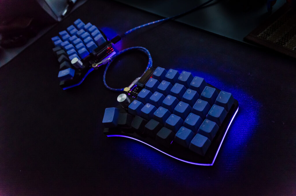
Anyway, I’ve already teased this keyboard in a previous project when I made a case for it. The making of this keyboard started about a year ago, and yet, it is still not completely finished. Now it is at least finished on the hardware level. I’ve been postponing this part for a really long time because it is tedious as I’ve said earlier. The reason I wanted the RGB on this keyboard is because, obviously, you’re 10% better at any game when you have RGB. Okay, I admit, I want it just because it looks cool, and you can’t deny it. That is also the reason I got custom keycaps, made custom cables, and designed a custom case for this keyboard. Now all that is left is to polish the software. There are a couple of features I wish to add, and I can touch up the layers a little bit more, to make the keyboard easier to use.
Since most people don’t own (or probably haven’t ever seen) a keyboard like this, I should probably explain what are these layers I’m talking about. As you can see, this keyboard doesn’t have as many keys as a full, standard keyboard. To combat this, you can program it so you have different layers which send different keystrokes depending on which layer is active. For example, I have a calculator layer, because I don’t like typing numbers on the top row. So when I’m on the base layer, U, I and O are the letters U, I and O, but on the calculator level, they are numbers 4, 5 and 6. This is the beauty of custom keyboards, you can customize them any way you wish. You can program them to do whatever you wish and think would make your experience better. People usually think it is hard to get used to these layers and unusual layouts, but the truth is that it takes a couple of weeks at most, and then it is actually much better and easier than standard keyboards because you move your fingers much less.
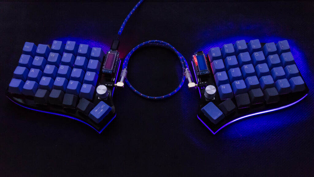
When I’ve said the hardware part is done, I lied a little bit. It seems like I haven’t soldered something properly, so the bottom row of LEDs doesn’t light up on the left half of the keyboard. So I’ll have to fix that, but I don’t think I’ll be in a hurry about that. You can see the problem in the picture below, light is much stronger under the right half than the left.
Boring stuff
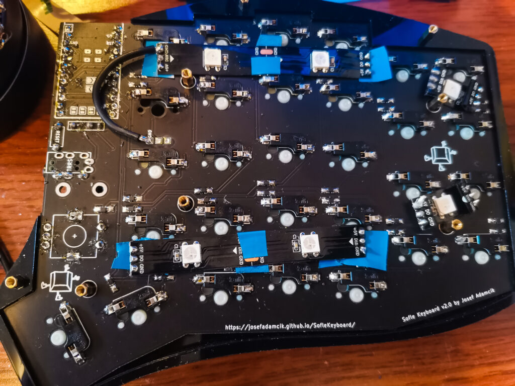
I started by laying out the LEDs the way I want to solder them. The Sofle board I used is great, but it seems that LEDs were a bit of an afterthought, so the support for them is not great. You can put them wherever you find a spot for them. I used 6 diodes cut in groups as you can see in the photo. Since I’m just taping them directly to the PCB, I used electrical tape on the spots where it seemed like there is a potential for shorts.
After that, I added solder to all the contact points for the LEDs.
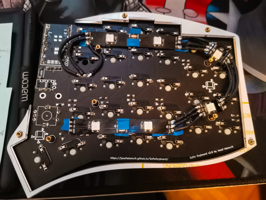
And now comes the most tedious part, soldering all the wires. The individual steps are these:
– measure the length of the wire
– cut
– strip the ends
– put the wire in the helping hands
– add the solder on the ends of the wire
– add the solder to the LED pads
– solder
Add a couple of mistakes, thicker wires than you would like, and a not great mood to begin with and you get a not too fun 2 hours of work. I tried to route the wires around other components on the PCB, but at some places, it simply wasn’t possible.
The last part is the software, but I won’t give you details on it because it is not really finished. I did just enough to test it out. I will make it functional some other day.