This is maybe the project that gave me the most trouble during this whole challenge. I first started working on it in September, but I couldn’t make it work the way I wanted to so I left it for later. And of course, since this is a project that I had to do, I couldn’t just discard it, so naturally, I left it for the very end of the project. The reason why I had to do it will be obvious in the next project, so stay tuned. But, what I didn’t know when I’ve left it for the end is how busy the end of December will be for me. This week, I’d just got back from a trip, had to go to my hometown for this weekend, and had to start packing since I’m moving next week. As you can imagine, this doesn’t leave much room for a project that was already troublesome.
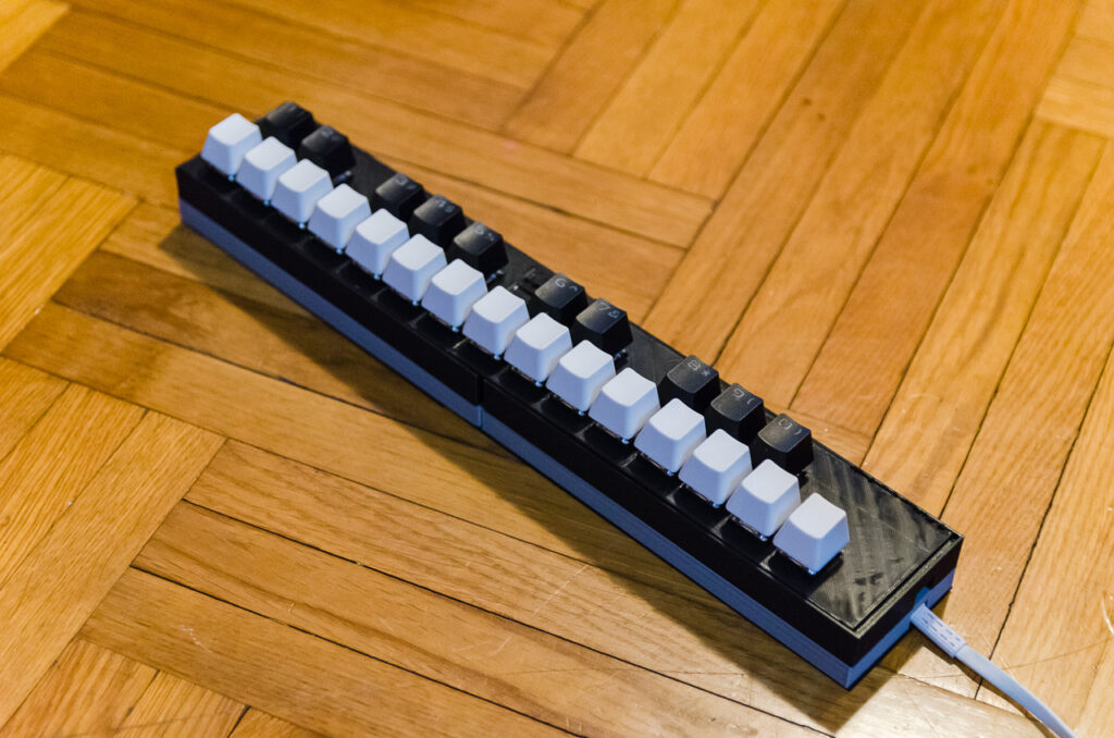
What I ended up making is actually far from my original plans. I wanted to modify a children’s piano toy into a MIDI keyboard. For those who don’t know what a MIDI keyboard is, it is basically a piano keyboard that communicates with your computer and music production software on it. This allows you to record notes in the software by playing them on the keyboard. And the fun part is that there are libraries with hundreds of instruments from which you can choose. But, the thing with the MIDI keyboards is that they are expensive, and I don’t really require one since I’m not a musician and don’t know anything about music production. So, me being who I am, my first reflex is – let’s just make one. I found this tutorial on YouTube which seemed quite easy to follow. Unfortunately, I hit a dead end on that road so I had to pivot. I tried a slightly different approach like in this video, but that didn’t work either. In the end, I had to fall back to something I’m comfortable with – keyboards. And that is what this is, just a slightly different version of it. That path has led me to the almost completely functioning MIDI keyboard. You can see a short demo in the video below. (I recommend watching till the end, it’s only 30 seconds anyway)
As you can see, if you watched until the end, not all the keys worked. To be precise, two-fifths of them. I’ll explain why in the boring stuff, but I ran out of time, so I couldn’t fix it in time for this post. In the end, I got a semi-functional MIDI keyboard, but hopefully, I will manage to fix it soon.
Boring stuff
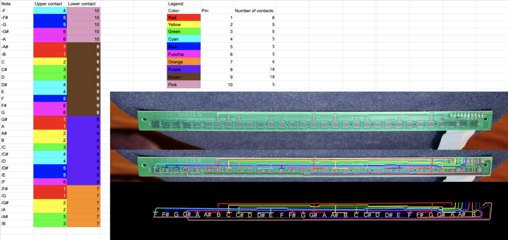
Let’s start with my first try. The plan was to buy a toy synthesizer and wire it into an Arduino, write some code and that’s it. Easy, right? Well, as I quickly discovered, not all synthesizers are made equal. The one in the tutorial had its keys wired into a matrix of rows and columns which is a very logical way to make a keyboard. Considering that, you can imagine how confused I was when I discovered that wasn’t the case here. I had to take a picture of the PCB and follow all the traces in Photoshop to figure out what was happening, but I found out that most of the keys were sharing the pins with another key. This was bad because the solution I was trying wouldn’t work at all. It very much relied on the matrix structure.
Thanks to Reddit, I found out that the way this keyboard worked was because there were different resistance values between the keys. I tried to use that as information to detect which key is pressed when, but my electronic skills aren’t that great so I had no luck there. The ideas I had, just wouldn’t work. I’m sure this can be done, and with more time maybe I would figure it out too, but as it stood in this case, I had to pivot. First, I tried my luck and bought another keyboard, a little bit more expensive than the first, hoping that my first one was the exception but I had no luck. It was wired exactly the same. The next idea was to solder the pads directly to a keyboard I had lying around like in this tutorial here. Here I don’t know if it was my mistake, or my board was significantly different from the one in the tutorial, but I couldn’t solder the wires to the pads whatever I tried.
In the end, I had to pivot to something I was comfortable with and had a reasonable expectation it would work – a custom mechanical keyboard. I had all the parts I needed since I already have plans to make a different custom keyboard regardless of this project so that made things a bit easier.
I started with a great online tool called keyboard-layout-editor.com and made my layout which you can see here. With this tool, you can configure the layout of your keyboard and even try out color schemes if you want. The main thing is that you can export the JSON file of the layout and copy it to a different tool for the next step.

The next tool is a case and plate builder – builder.swillkb.com. Since this is a very custom keyboard, I had to have somewhere to put the keys in, and this tool allows us to generate a plate for the keyboard from the layout in the previous step. As you can see in the picture below, I also used this to plan out the connections between the keys. The red lines are rows and the other ones are columns.

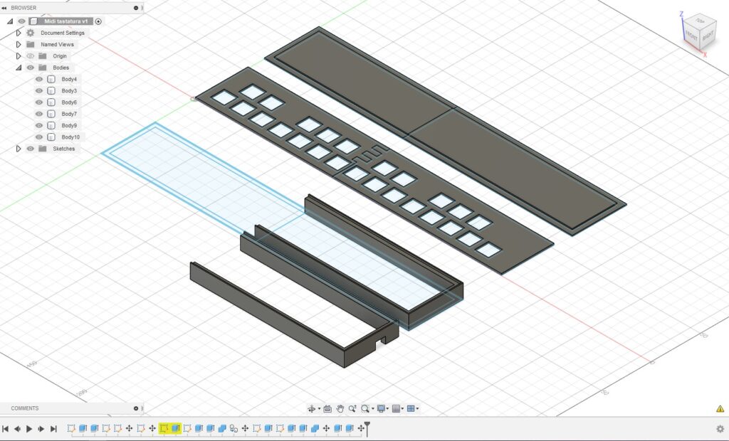
Using the file I got in the previous step, I designed a very simple case to 3D print. (It is divided in half because it is too large to be printed in one piece on my printer). There are three parts here: the plate, which is just the file from the previous step extruded to be 1.6mm thick, the sides 3.5mm wide with a 10x6mm cutout for the USB, and the bottom. I ended up having to print another copy of the sides to stack them on each other since the first one wasn’t high enough. Splitting this into multiple parts is also good because if something fails, I don’t have to print the whole thing again.
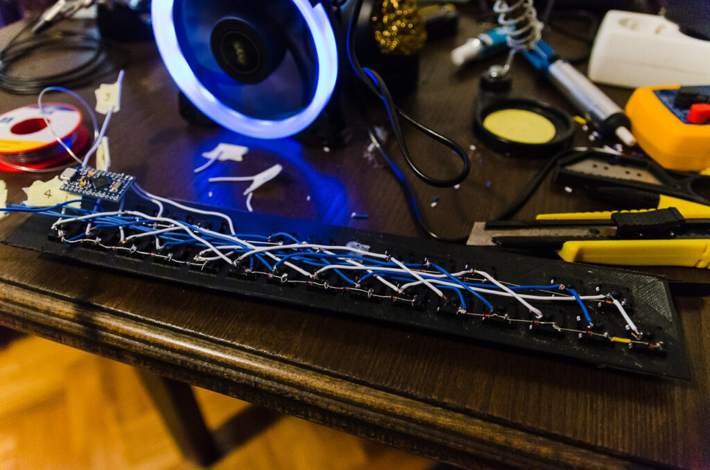
Once the plates were printed I could go on to the most difficult part of the project – hand wiring the keyboard. What this means is that I had to solder every column and row of switches. QMK has a great guide for hand wiring so if you ever plan to do something like this I would recommend that guide. I started by connecting keys in the rows with diodes. They are a really important part because they prevent ghosting which is an effect where the computer registers keystrokes that you haven’t made because of the way they are wired. This is important when you press multiple keys at once, which you do when playing chords on the piano.
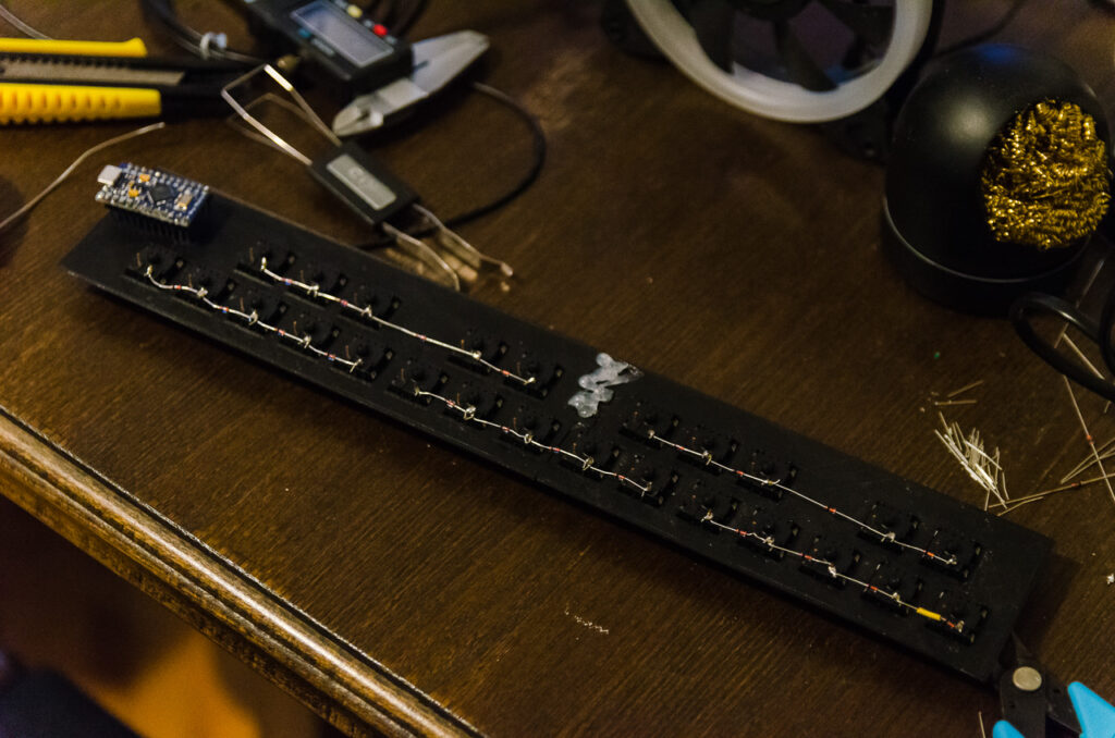
And then comes the hardest part of the most difficult part – soldering the columns. Normally this wouldn’t be so much harder than the rows, but, because my columns aren’t under each other this makes things complicated. Since they are staggered and next to each other, that means I had to criss-cross the wires between the switches. That isn’t a huge problem in the beginning but it gets real complicated real fast. It didn’t help that I chose a thick wire with a solid core. I thought that would make things easier, but it did the opposite. Maybe it’s because the wire was too thick, but it was brittle and not flexible enough so it was hard to shape it the way I needed.
After soldering the rows, all that is left is to connect every row and column to the micro-controller. I used Pro Micro because I had one on hand for the aforementioned keyboard project that I have in the plans. That controller is often used for custom keyboards because it’s cheap, easy to work with, and gives you all the features that you need for a custom keyboard.
The last step is writing the code. First I tried to modify the code from the first tutorial I linked but that didn’t work too well for me. And since I don’t have much experience with that code, once again I went back to the custom keyboards world. I used QMK which is the most commonly used firmware in custom keyboards. And because I was too lazy to write the whole code for my keyboard, I found one that is called 25 by 40percent.club. This one fits my needs because it is a split keyboard with 25 keys on each side which are wired in a 5×5 matrix, just like mine. I just edited the config.h file to change the pins that I connected the micro-controller to and then edited the keymap so it works as I want it to.
/* Copyright 2018
 *
 * This program is free software: you can redistribute it and/or modify
 * it under the terms of the GNU General Public License as published by
 * the Free Software Foundation, either version 2 of the License, or
 * (at your option) any later version.
 *
 * This program is distributed in the hope that it will be useful,
 * but WITHOUT ANY WARRANTY; without even the implied warranty of
 * MERCHANTABILITY or FITNESS FOR A PARTICULAR PURPOSE.  See the
 * GNU General Public License for more details.
 *
 * You should have received a copy of the GNU General Public License
 * along with this program.  If not, see <http://www.gnu.org/licenses/>.
 */
#include QMK_KEYBOARD_H

// Each layer gets a name for readability, which is then used in the keymap matrix below.
// The underscores don't mean anything - you can have a layer called STUFF or any other name.
// Layer names don't all need to be of the same length, obviously, and you can also skip them
// entirely and just use numbers.
#define _QWERTY 0
#define _LOWER  1

enum custom_keycodes {
  QWERTY = SAFE_RANGE,
  LOWER,
};

const uint16_t PROGMEM keymaps[][MATRIX_ROWS][MATRIX_COLS] = {
  /* Qwerty
   * ,---------------------------------------------------------------------.
   * |   1  |   2  |   3  |   4  |   5  |   6  |   7  |   8  |   9  |   0  |
   * |------+------+------+------+------+------+------+------+------+------|
   * |   Q  |   W  |   E  |   R  |   T  |   Y  |   U  |   I  |   O  |   P  |
   * |------+------+------+------+-------------+------+------+------+------|
   * |   A  |   S  |   D  |   F  |   G  |   H  |   J  |   K  |   L  | Bksp |
   * |------+------+------+------+------|------+------+------+------+------|
   * |   Z  |   X  |   C  |   V  |   B  |   N  |   M  |   ,  |   .  |Enter |
   * |------+------+------+------+------+------+------+------+------+------|
   * | Ctrl | GUI  | Alt  |Lower |Space | Shift| Left | Down |  Up  |Right |
   * `---------------------------------------------------------------------'
   */
  [_QWERTY] = LAYOUT_split(
    KC_A,    KC_S,    KC_D,    KC_F,    KC_G,    KC_Y,    KC_U,    KC_I,    KC_O,    KC_P,    \
    KC_W,    KC_E,    KC_T,    KC_Y,    KC_U,    KC_LSFT, KC_LEFT, KC_DOWN, KC_UP,   KC_RGHT, \
    KC_H,    KC_J,    KC_K,    KC_L,    KC_SCLN, KC_N,    KC_M,    KC_COMM, KC_DOT,  KC_ENT,  \
    KC_O,    KC_P,    KC_Z,    KC_X,    KC_B,    KC_6,    KC_7,    KC_8,    KC_9,    KC_0,    \
    KC_N,    KC_M,    KC_COMM, KC_DOT,  KC_SLSH, KC_H,    KC_J,    KC_K,    KC_L,    KC_BSPC \


  ),

  /* Lower
   * ,---------------------------------------------------------------------.
   * |  F1  |  F2  |  F3  |  F4  |  F5  |  F6  |  `   |   /  |   _  |   +  |
   * |------+------+------+------+------|------+------+------+------+------|
   * |  F7  |  F8  |  F9  |  F10 |  F11 |  F12 |  ~   |   [  |   ]  |  \   |
   * |------+------+------+------+-------------+------+------+------+------|
   * | Esc  |      |      |      |      |      |      |   ;  |  "   |  Del |
   * |------+------+------+------+------|------+------+------+------+------|
   * | Tab  |      |      |      |      |      |      |      |      |      |
   * |------+------+------+------+------+------+------+------+------+------|
   * |      |      |      |      |      |      | Home | PgDn | PgUp | End  |
   * `---------------------------------------------------------------------'
   */
  [_LOWER] = LAYOUT_split( \
    KC_F1,   KC_F2,   KC_F3,   KC_F4,   KC_F5,   KC_F6,   KC_GRV, KC_SLSH, KC_UNDS, KC_PLUS, \
    KC_F7,   KC_F8,   KC_F9,   KC_F10,  KC_F11,  KC_F12,  KC_TILD, KC_LBRC, KC_RBRC, KC_PIPE, \
    KC_ESC,  _______, _______, _______, _______, _______, _______, KC_SCLN, KC_QUOT, KC_DEL,  \
    KC_TAB,  _______, _______, _______, _______, _______, _______, _______, _______, _______, \
    _______, _______, _______, _______, _______, _______, KC_HOME, KC_PGDN, KC_PGUP, KC_END   \
  ),
};

bool process_record_user(uint16_t keycode, keyrecord_t *record) {
  return true;
}

void matrix_init_user(void) {

}

void matrix_scan_user(void) {
}

void led_set_user(uint8_t usb_led) {

}
When you are done with your code, you need to flash it on the Pro Micro. You do that with QMK Toolbox, but again, there are detailed instructions on the QMK website.
I had no issues with these steps, but when I flashed the firmware, I’ve noticed that two of the columns aren’t working. This is most likely an error I made in the soldering, but I couldn’t find it. I’ve tested everything with a multimeter but everything seemed fine. Unfortunately, this is where I ran out of time to work on the project so I was forced to leave it at that for now. Hopefully, I will find the problem and fix it in the future.